

 English
 中文简体
1: Introduction – Enhancing Comfort and Convenience with Car Armrests The Importance of Comfort in Modern Driving In today’s automotive landscape,...
READ MORENov 16, 2026
A retrofit shop sends a power seat module back with a scorched housing and a complaint about random position loss. The module itself is fine. The fault sits in one Micro-Fit 3.0 cavity, where the conductor crimp was closed with a generic plier-style tool, half the strands were cut, and resistance climbed until the terminal browned out under load.
Micro-Fit 3.0 is one of the most dependable small power interfaces you can put inside a vehicle, but only when three things line up: the terminal matched to the wire gauge, a ratcheted crimp tool with the correct die, and a housing that matches the header's keying and circuit count. Miss any one of them and the failure surfaces months later, usually in a warranty claim rather than on the bench.
Content
Micro-Fit 3.0 is a 3.00 mm pitch wire-to-wire and wire-to-board connector family, offered in single-row and dual-row layouts from 2 up to 24 circuits. Terminals accept roughly 20 to 30 AWG, housings latch positively, and terminal position assurance (TPA) retainers prevent a partly seated terminal from backing out under vibration. It sits in the useful gap between 2.00 mm signal connectors, which cannot carry real current, and 4.2 mm power connectors, which consume board space a compact module does not have.
| Parameter | Typical Value | What It Means in Practice |
|---|---|---|
| Pitch | 3.00 mm | Hand-solderable on 0.8 mm and 1.6 mm boards; forgiving of assembly tolerance |
| Layouts | Single row, dual row | Dual row halves the footprint for the same circuit count |
| Circuit counts | 2 to 24 | Above 12 circuits, dual row is usually the only practical option |
| Wire range | About 20 to 30 AWG | 18 to 22 AWG covers seat motors, lighting and relay loads |
| Current per circuit | Up to 8.5 A, derated | Falls sharply with circuit count, ambient temperature and smaller wire |
| Voltage rating | Up to 600 V | Far beyond any 12 V or 24 V automotive circuit |
| Temperature range | Minus 40 to 105 degrees C | Covers cabin and most under-dash locations; not an engine-bay part |
| Mating styles | Wire-to-wire, wire-to-board | Vertical and right-angle headers available for either approach |
| Retention | Positive latch plus optional TPA | TPA is worth specifying in any seat or door application |
The headline figure of 8.5 A per circuit is a best case measured on a single circuit with a large conductor. Put the same terminal into a 20-circuit dual-row housing inside a closed armrest box and the realistic continuous figure drops considerably. Design to the derating curve, not to the catalogue maximum.
A Micro-Fit 3.0 "connector" is not one part number. It is four purchased items that must be quoted together, and quoting only the housing is the most common ordering mistake we see on incoming purchase orders.
The dual-row pair most often quoted carries the 43025 receptacle and 43020 plug designations, with single-row equivalents for smaller circuits. Keying options prevent two identical housings from being cross-mated, and panel-mount ears allow the connector to be fixed to a bracket instead of hanging on the harness.
Receptacle terminals (43030) and plug terminals (43031) are separate parts, and each exists in more than one wire range plus tin and gold plating. Tin is fine for interior electronics; gold is worth the premium on low-current signal pins that will see repeated mating cycles or a humid environment.
Board-side headers (43045 and relatives) come vertical or right angle, through-hole or surface mount, with or without locking ramps. The header must match row count, circuit count and keying option, and on surface-mount versions the solder-paste stencil aperture matters more than most designers expect.
The TPA retainer clicks in after the terminals are seated and physically blocks a backed-out terminal. On a seat frame that sees thousands of vibration cycles, it is cheaper than a field return. Combine it with a boot or a tie-down point within 50 mm of the housing so the loom cannot flex directly at the crimp.
Decide current first, then wire, then circuit count. A rule that works well in cabin electronics: 22 AWG for signal and sensor runs, 20 AWG for switch and illumination circuits, 18 AWG for motor and relay loads. Skinny wire on a motor circuit is not a small saving; 22 AWG carries roughly 53 milliohms per metre, so 5 A through one metre out and back costs about half a volt, and that voltage drop becomes heat at the terminal rather than torque at the motor.
Circuit count then follows from the harness, not from what is on the shelf. A dual-row 16-circuit housing occupies about the same board area as a single-row 8-circuit part, which is why dense modules almost always go dual row. Leave two spare cavities on any new design if the enclosure allows it; adding a function later without redesigning the header is worth more than the small cost of the extra positions.
The terminal is only as good as the press that formed it. A proper Micro-Fit crimp shows conductor strands in the inspection window, an insulation crimp that grips the jacket without cutting into it, and no strand damage at the transition. If strands are severed, the remaining cross-section carries the full load and heats up; if the insulation crimp is loose, flexing fatigue breaks the conductor behind the terminal.
Three practical rules keep yield high:
Record crimp height on the setup sheet as well. It is the single measurement that predicts pull force, and it is the first thing to check when a batch starts failing intermittently.
Pitch class should follow current, not habit. Moving a 6 A lighting circuit onto a 2.00 mm connector to save space usually ends with a warm housing and a rework order.
| Pitch Class | Typical Current per Circuit | Usual Wire | Where It Makes Sense |
|---|---|---|---|
| 1.25 to 1.50 mm | About 1 to 2 A | 26 to 30 AWG | Display ribbons, sensor boards, tight signal routing |
| 2.00 mm | About 2 to 3 A | 24 to 28 AWG | Switch panels, dense interior looms, low-power lighting |
| 3.00 mm (Micro-Fit 3.0) | Up to about 8.5 A | 18 to 24 AWG | Seat modules, ambient lighting drivers, relay outputs, armrest electronics |
| 4.20 mm and above | About 9 to 13 A | 16 to 18 AWG | Main power feeds, battery distribution, high-current accessories |
The family turns up wherever a module needs a few amps per channel but cannot afford a 4.2 mm footprint: seat control boxes, armrest touch panels, heated seat pads, ambient lighting controllers and the short harness that links them. Because it is available in wire-to-wire as well as wire-to-board form, the same terminal system can run from a door switch to an inline joint and from the joint into the module, which keeps tooling and spare terminals to a single family.
That is the practical argument for standardising on it. A retrofit project that mixes three connector families needs three sets of dies, three sets of spares and three sets of inspection criteria. One family, one crimp height, one training session.
For builders assembling complete looms rather than bare connectors, the harness itself is the variable that decides reliability, and an engine-specific build with sealed splices and documented pinouts removes most of the guesswork. If you want the module side of the circuit explained in more depth, our notes on vehicle control module functions, components and diagnostics cover the surrounding architecture.
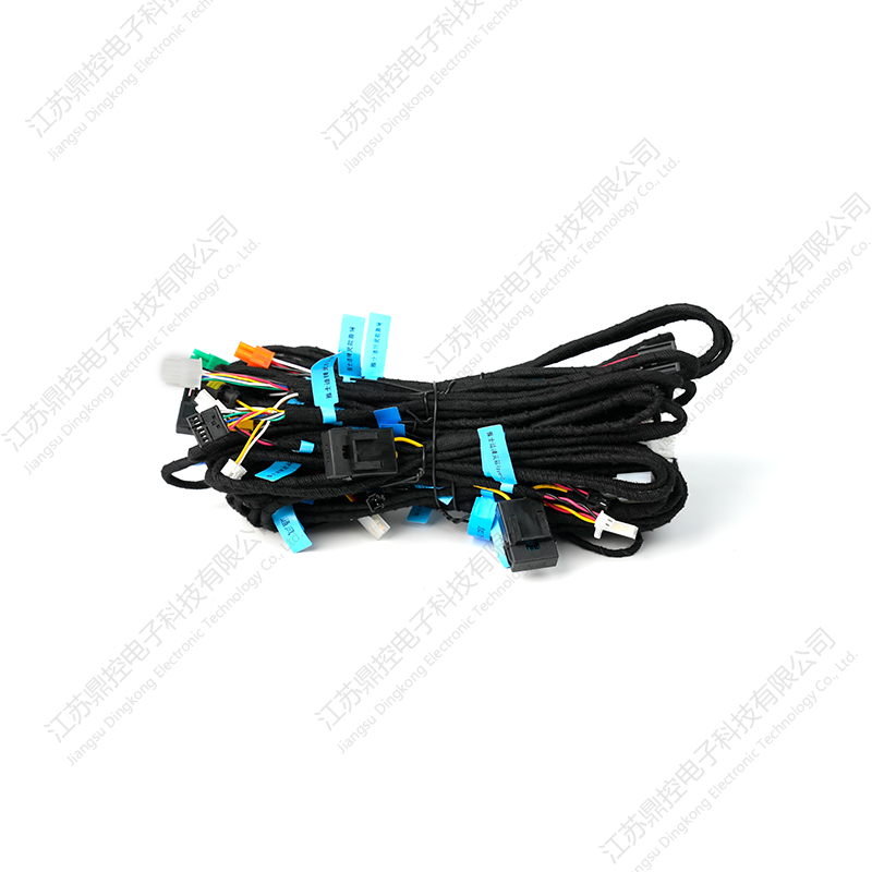 Custom Vehicle Wiring Harness for Tesla, Benz and BMWCustom harness for Tesla, Mercedes-Benz and BMW uses tin-plated oxygen-free copper, IP67 protection and original plug-in connectors for replacement or modification builds.View Product →
On the module side, a control unit with multiple relay outputs and an IP65 housing is the usual partner for a 3.00 mm interface, because the connector has to survive the same dust and splash conditions as the enclosure it enters.
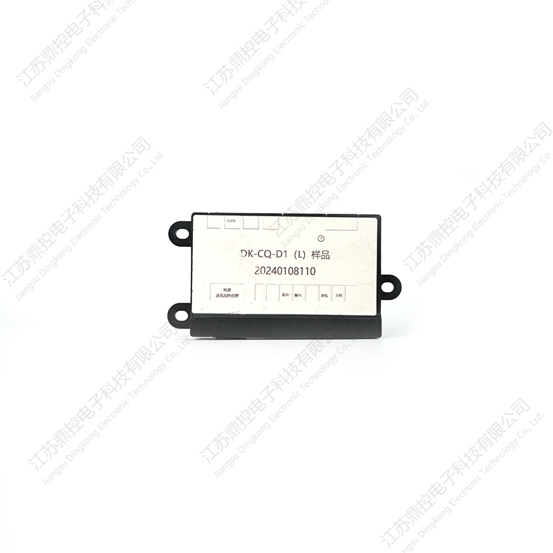 DK-7.0 Vehicle Control Unit - IP65 DustproofThe DK-7.0 vehicle control unit is a high-performance core designed specifically for automotive electronic retrofits. Whether it's luxury seat systems, ambient lightin...View Product →
The same logic applies to interior control surfaces. A capacitive panel that replaces a row of physical buttons still needs a robust power and data interface behind the glass, and the connector is often the part with the least design attention and the highest field-failure share. Seat adjustment is a good illustration of how many functions end up sharing one small connector body, as covered in our guide to electric seat features, installation and maintenance.
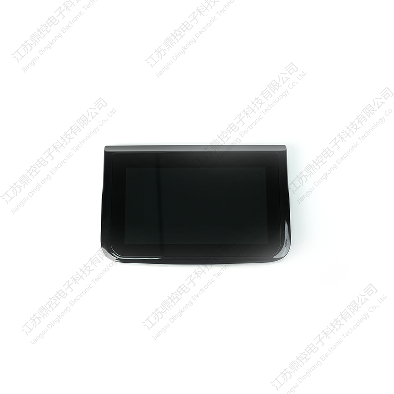 7 Inch Automotive Capacitive Touch Screen DisplayA 7-inch automotive capacitive display with 10-point touch, IPS wide viewing angle, IP65 protection and custom UI options for control-surface designs.View Product →
Five lines in a specification prevent most disputes on a connector order:
Ask for the datasheet revision number as well. Terminal plating and housing material change quietly between revisions, and a harness approved against last year's drawing may not match this year's part. For assemblies, also fix the harness length tolerance, typically plus or minus 10 mm on cabin looms, and specify the flex point so the crimp is never the first thing to bend.
Micro-Fit 3.0 earns its place in vehicle electronics because it balances current capacity, footprint and an assembly process that can be controlled on a bench. The connector is rarely the weak link; the crimp, the wire choice and the derating calculation are.
Treat the terminal, tool and wire as one system, write the acceptance numbers into the purchase order, and the same 3.00 mm interface will outlast the vehicle it was fitted to.
1: Introduction – Enhancing Comfort and Convenience with Car Armrests The Importance of Comfort in Modern Driving In today’s automotive landscape,...
READ MOREI. IntroductionThe automotive industry is undergoing constant evolution, with a growing emphasis on vehicle maintenance and personalization. For car o...
READ MORE1. Introduction The Tesla Model 3 and Model Y have quickly become two of the most popular electric vehicles on the market. With their sleek designs, i...
READ MORE
Jiangsu Dingkong, No.1, Menlouxia, Changjing Town, Jiangyin City, Jiangsu Province, China
Copyright © 2024 Jiangsu Dingkong Electronic Technology Co., Ltd. All Rights
Reserved.
 Auto Aftermarket Accessories Manufacturers