

 English
 中文简体
1: Introduction – Enhancing Comfort and Convenience with Car Armrests The Importance of Comfort in Modern Driving In today’s automotive landscape,...
READ MORENov 12, 2026
A crank-no-start complaint or a P0335 code often sends people straight to the parts counter. That is an expensive shortcut. On most two-wire crank sensors, a multimeter can tell you a lot before you buy anything: whether the sensor coil is open or shorted, whether it generates AC voltage while the engine cranks, and whether the wiring is hiding a break. The catch is that a two-wire crank sensor is usually a passive inductive sensor, not a powered Hall-effect sensor, so the test procedure is different from a three-wire sensor.
The short answer: disconnect the sensor and check resistance across its two terminals against the manufacturer's specification, then reconnect it and watch for AC voltage while cranking. If resistance is correct but AC voltage is absent, do not condemn the sensor until you have checked cranking speed, the reluctor ring, the air gap, and the harness.
Content
Two wires at the connector are a strong clue, not a guarantee. Most two-wire crankshaft position sensors are variable-reluctance sensors: a coil and a magnet inside the sensor, with a toothed reluctor ring passing the tip. The sensor generates its own AC signal, so it does not need a power feed. A three-wire Hall-effect sensor, by contrast, needs power, ground, and a signal circuit, and its output is a switching voltage.
Before probing, identify the sensor by its connector, mounting position, and service data. If the wiring diagram shows a shielded pair going directly to the ECM with no power feed, you are probably dealing with an inductive sensor. If the diagram shows a reference voltage, it is not a passive two-wire sensor and the resistance test may be meaningless. This distinction matters because the wrong test can make a good sensor look bad, or make a bad one look good.
A digital multimeter is the right first instrument because it is fast, safe, and good at finding open coils, shorted turns, and broken wiring. It is not a replacement for a lab scope when the fault is intermittent or heat-related. The table below shows the useful checks and their limits.
| Check | Meter setting | What a pass looks like | What it does not prove |
|---|---|---|---|
| Resistance across sensor pins | Ohms, sensor disconnected | Within the manufacturer's range and steady during a wiggle test | Signal quality under heat, vibration, or high RPM |
| Insulation to ground | Ohms, each pin to clean engine ground | Open circuit, no continuity | A partial short that appears only when hot |
| AC voltage while cranking | AC volts, sensor connected, back-probed | AC voltage rises with cranking speed and remains stable | Exact waveform shape or missing pulses |
| Harness continuity | Ohms, sensor and ECM disconnected as needed | Near-zero ohms end to end, no short to ground | Terminal tension and interference problems |
| Air gap and reluctor | Visual check and non-magnetic feeler gauge | Clean ring, correct gap from service data | Cracks or damage hidden behind the ring |
You do not need a full diagnostic bay, but you do need the right small items and a safe way to crank the engine without it starting. A charged battery matters more than many people expect, because a slow crank can produce a weak AC signal and send you chasing the wrong fault.
Do not pierce insulation unless there is no safe back-probe access. A pinhole lets moisture into the harness and can create a new intermittent fault after the repair. Use the connector's rear seals, a breakout lead, or the correct terminal probe.
Use min/max or peak-hold if the meter has it, because the AC voltage pulse is brief. A meter that averages slowly may show a lower value than a scope would capture, especially during a slow crank.
Resistance tells you whether the coil is intact. An open circuit, a very high reading, or a reading that jumps while wiggling the harness points to a failed sensor or a broken lead. A reading outside the service range is a red flag, but a reading inside the range is not the final answer. Heat, vibration, and a weak magnet can still cause a signal dropout that a cold resistance test will miss.
AC voltage tells you whether the sensor is generating a signal. If the sensor produces a clean AC rise during cranking but the ECM still reports no RPM, move to the harness and ECM side. If the sensor produces no AC voltage but resistance is correct, check cranking speed, air gap, and reluctor condition before replacing it.
When the repair moves beyond a simple pigtail to a complete harness or custom electrical assembly, a made-to-spec part is often more reliable than repeated splice repairs.
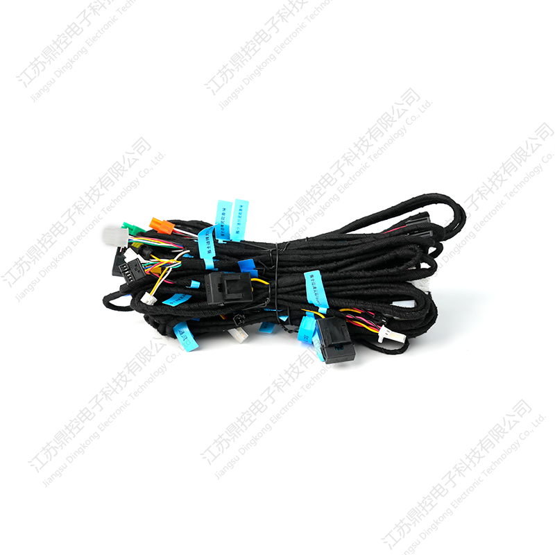 Custom Automotive Wiring Harness for Tesla, Mercedes-Benz, and BMWA made-to-spec harness for Tesla, Benz, and BMW that supports OEM replacement or performance modifications with plug-and-play connectors and customizable length and color coding.View Product →
An intermittent no-start that only appears hot, or a signal that drops out at a specific RPM, needs a scope or a capable scan tool with graphing. A multimeter shows an average or a brief sample, but a scope shows the waveform, missing teeth, noise, and amplitude changes. If the signal disappears between the sensor and the ECM, the next step is circuit-level diagnostics rather than another sensor; this guide to control module diagnostics explains how the module side is organized.
The practical rule is simple: test the two-wire crank sensor as a generator, not as a powered switch. Confirm the sensor type, measure resistance against the correct specification, check for shorts, and watch AC voltage while cranking. If those checks pass, move to the reluctor ring, air gap, harness, cranking speed, and ECM signal path. That sequence saves parts and, more importantly, saves the time spent replacing a sensor that was never the problem.
1: Introduction – Enhancing Comfort and Convenience with Car Armrests The Importance of Comfort in Modern Driving In today’s automotive landscape,...
READ MOREI. IntroductionThe automotive industry is undergoing constant evolution, with a growing emphasis on vehicle maintenance and personalization. For car o...
READ MORE1. Introduction The Tesla Model 3 and Model Y have quickly become two of the most popular electric vehicles on the market. With their sleek designs, i...
READ MORE
Jiangsu Dingkong, No.1, Menlouxia, Changjing Town, Jiangyin City, Jiangsu Province, China
Copyright © 2024 Jiangsu Dingkong Electronic Technology Co., Ltd. All Rights
Reserved.
 Auto Aftermarket Accessories Manufacturers