

 English
 中文简体
1: Introduction – Enhancing Comfort and Convenience with Car Armrests The Importance of Comfort in Modern Driving In today’s automotive landscape,...
READ MORENov 02, 2026
A 24 AWG wire that pulls off a PCB pad after a few heat cycles is rarely a “bad solder” problem. The pad did not reach soldering temperature, the flux burned away before the joint formed, or the wire moved while the alloy solidified. The fix is not a bigger blob of solder. It is a repeatable process: clean the pad, add flux, tin the wire, heat the pad and wire together, feed solder into the joint, remove the iron, and let the joint freeze without movement. With a properly sized tip and 0.6–1.0 mm solder, a sound wire-to-board joint usually forms in 2–5 seconds.
That timing matters in vehicle electronics, where a joint may sit in a door harness, under a seat, or beside a control module that sees vibration and temperature swings. The electrical connection must be sound, and the wire must be supported so the solder fillet is not carrying mechanical load.
Content
A good joint has a smooth, concave fillet from the pad up to the tinned wire. The solder should wet the copper pad and the individual wire strands, not sit on top as a round ball. The edge of the pad should still be visible under the fillet, and there should be no crack, void, or bridge to a neighboring pad.
Leaded 63/37 solder often cools shiny. Many lead-free alloys cool to a satin or slightly dull surface, so dullness alone is not a defect. Reject the joint when it is grainy, cracked, balled up, sitting on an unwetted pad, or moving when the wire is gently flexed.
Use a temperature-controlled station in the 50–80 W class rather than a fixed 30 W pencil. For 63/37 leaded solder, a tip temperature around 315–340 C works for most small pads. For SAC305 lead-free solder, start around 340–370 C and adjust for pad size and copper mass. Use rosin or no-clean electronics flux, not acid-core solder or plumbing flux.
Tip shape matters as much as temperature. A 0.8–1.2 mm chisel tip suits 24–26 AWG signal wires. A 1.6–2.4 mm chisel tip transfers heat faster into 18–20 AWG power wires and larger pads. Keep the tip tinned and wipe it only when oxide or burned flux interferes with heat transfer.
| Wire size | Typical use | Tip width | Solder diameter | Iron setting |
|---|---|---|---|---|
| 26–24 AWG | Signal, sensor, small switch lead | 0.8–1.2 mm | 0.5–0.8 mm | 315–330 C |
| 22–20 AWG | General automotive Hook-up wire | 1.2–1.6 mm | 0.8 mm | 330–350 C |
| 18–16 AWG | Power feed, larger ground pad | 2.4 mm | 1.0–1.2 mm | 350–370 C |
These are starting points, not guarantees. A pad connected to a heavy copper plane pulls heat away quickly, while a thin flex circuit needs less heat and shorter contact time. When the joint is part of a production harness rather than a one-off repair, wire selection and connector termination matter as much as iron temperature.
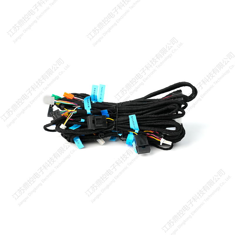 Vehicle Wiring Harness for Tesla, Mercedes-Benz, and BMWFor production harness work, this vehicle wiring harness offers oxygen-free copper conductors, high-temperature insulation, IP67 sealing, and model-specific plug-in connectors.View Product →
A production loom should use a correctly sized conductor, proper terminals, and a defined strain-relief method. Hand-soldered wire-to-board joints are best reserved for repairs, prototypes, or short internal jumpers where a connector is impractical.
Clean the pad with 90% or higher isopropyl alcohol before adding heat. If the copper looks oxidized, a light pass with a 600–800 grit abrasive stick can help, but stop before you wear through the pad. Apply a small amount of flux to the pad, not a flood that spreads across the board.
For a through-hole pad, feed the wire through the hole first, then solder from the opposite side so the barrel fills. Do not bend the wire sharply after soldering; that puts immediate stress on the pad and can crack the fillet.
Place the tinned wire on the tinned pad and add a touch of fresh flux. Bring the chisel tip into contact with both the pad and the wire at the same time. The pad is the heat sink, so it must receive direct contact, not just the wire.
If the solder does not flow within three seconds, stop. Check tip contact, tip size, pad oxidation, and heat setting. Reheating the same pad repeatedly is how lifted pads and damaged traces happen.
A wire-to-board joint is not finished when the solder freezes. Solder wicking creates a stiff transition point where the strands can fatigue. Use adhesive-lined heat shrink, a service loop, or a cable tie so the pad does not carry pull force. Avoid acid-cure silicone near electronics; use a neutral-cure adhesive or an approved conformal coating instead.
Clean no-clean flux residue if it is sticky or attracts dust, and inspect under 5–10x magnification. Check continuity from wire to pad and verify there is no short to adjacent pads. Bring power up on a current-limited supply, especially after rework on a vehicle control board.
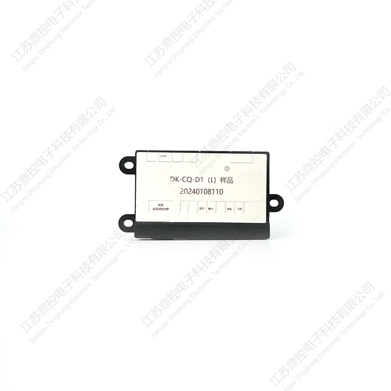 DK-7.0 IP65 Vehicle Control Unit for Electronic RetrofitsFor sealed control-module retrofits, this IP65 unit supports seats, ambient lighting, and soft-close doors with industrial-grade chipsets and anti-interference signal transmission.View Product →
When a repair moves into a sealed automotive control module, the housing, gasket, and connector retention matter as much as the solder joint. If the board is already potted or the pad has lifted across multiple traces, replacement is usually the lower-risk decision.
To separate a wiring fault from a module fault after repair, this guide to vehicle control module functions and diagnostics is a useful next step. The same discipline applies: measure, isolate, and do not assume a shiny joint is a reliable connection.
1: Introduction – Enhancing Comfort and Convenience with Car Armrests The Importance of Comfort in Modern Driving In today’s automotive landscape,...
READ MOREI. IntroductionThe automotive industry is undergoing constant evolution, with a growing emphasis on vehicle maintenance and personalization. For car o...
READ MORE1. Introduction The Tesla Model 3 and Model Y have quickly become two of the most popular electric vehicles on the market. With their sleek designs, i...
READ MORE
Jiangsu Dingkong, No.1, Menlouxia, Changjing Town, Jiangyin City, Jiangsu Province, China
Copyright © 2024 Jiangsu Dingkong Electronic Technology Co., Ltd. All Rights
Reserved.
 Auto Aftermarket Accessories Manufacturers