

 English
 中文简体
1: Introduction – Enhancing Comfort and Convenience with Car Armrests The Importance of Comfort in Modern Driving In today’s automotive landscape,...
READ MOREOct 20, 2026
A 35 mm2 orange cable rated at 300 V will not survive a 400 V pack, no matter how clean the crimp looks. Most electric vehicle wiring problems trace back to the same three mismatches: an insulation class below system voltage, a connector without a high-voltage interlock loop, or a shield terminated at one end only. Get those three right and the rest of the harness becomes a routing and serviceability exercise rather than a reliability gamble.
The sections below separate traction wiring from low-voltage control wiring, show the numbers that actually matter in a specification, and point out where procurement risk usually hides.
Content
Start with the voltage domain, not the wire gauge. A plug-in hybrid pack may sit between 100 V and 200 V, while a battery-electric pack commonly runs at 400 V, and 800 V platforms are now common on new models. At the same time, seats, lighting, displays, and body electronics still run on 12 V, 24 V, or 48 V. The two domains share a chassis but almost nothing else: different insulation, different connectors, different test routines, and frequently different suppliers.
| Attribute | High-voltage traction wiring | Low-voltage and control wiring |
|---|---|---|
| System voltage | 400 V to 800 V DC, up to 1,000 V on some platforms | 12 V, 24 V, or 48 V DC |
| Conductor size | 16 mm2 to 95 mm2 typical | 0.35 mm2 to 6 mm2 typical |
| Insulation material | Cross-linked polyethylene or silicone, rated 600 V or 1,000 V | PVC, polyethylene, or cross-linked polyethylene, rated 60 V to 300 V |
| Jacket color | Orange, as an electrical hazard identifier | Black or function-coded colors |
| Connector features | Two-stage latch, touch-safe contacts, keying, interlock loop | Sealed or unsealed housings, retention clip, terminal position assurance |
| Shielding | Foil plus braid, terminated 360 degrees at both ends | Twisted pairs only where CAN or Ethernet needs them |
| Primary failure mode | Dielectric breakdown, connector overheating, arc events | Voltage drop, terminal corrosion, induced noise on signal lines |
Because the requirements diverge this sharply, a supplier who is excellent at 12 V body harnesses is not automatically qualified for traction cable assemblies, and the reverse is just as true. When one vendor handles both, the practical benefit is interface control: the low-voltage branch that powers a battery cooling pump and the high-voltage feed to that pump are then designed against the same routing and temperature assumptions.
Three properties decide whether a traction cable survives its service life. The first is insulation class. Automotive single-core high-voltage cables are commonly rated 600 V or 1,000 V, with cross-linked polyethylene as the usual dielectric and silicone used where cable temperatures reach around 180 degrees Celsius near inverters or DC-DC converters. A cable rated at only 300 V has no place in a 400 V system, even when the measured current looks modest, because partial discharge and tracking begin long before a hard short appears.
The second is shielding. Traction cables carry switched currents with very fast voltage transitions, and an unshielded run radiates broadband noise into the vehicle's own sensor wiring and radio reception. A foil-plus-braid construction terminated 360 degrees at both ends contains that energy. A shield grounded at one end only turns the cable into an antenna, which is one of the most common and least obvious mistakes in aftermarket builds.
The third is the connector interface: a two-stage latch, touch-safe finger-proof contacts, keyed housings that prevent cross-mating, and an interlock loop that tells the controller the connector is fully seated before the contactors close. Mated sealing of IP67 is a reasonable baseline, with IP6K9K where steam cleaning is expected.
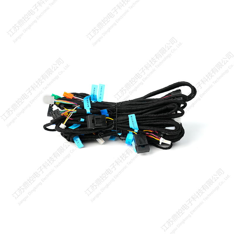 Custom Automotive Wiring Harness for Tesla, Mercedes-Benz, and BMWVehicle-specific harness for Tesla, Mercedes-Benz, and BMW, built to drawing with oxygen-free copper conductors and IP67 sealing for reliable power and signal transmission.View Product →
Because conductor cross-section, insulation class, and connector family change from platform to platform, harnesses for Tesla, Mercedes-Benz, and BMW models are normally built to a vehicle-specific drawing rather than selected from a catalog. That is the right starting point whenever a project needs a defined assembly with traceable materials instead of loose cable cut to length on site.
Nothing in the cabin moves without the low-voltage network. Seat adjustment, armrest displays, ambient lighting, door locks, and body control all depend on harnesses that carry power and data together. Where a traction cable is judged on dielectric strength and ampacity, a low-voltage harness is judged on voltage drop, connector retention, and signal integrity.
Data is where late-stage surprises appear. CAN FD and LIN remain the workhorses, while 100BASE-T1 and 1000BASE-T1 Ethernet links require controlled-impedance twisted pairs, matched pair lengths, and physical separation from traction runs. A drop of half a volt across a seat motor feed is harmless; the same amount of induced noise on a current sensor line is not.
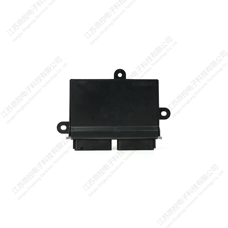 DK-B-1947 Vehicle Control Unit for Automotive ModificationIP65-rated control unit for seats, ambient lighting, and electric suction doors, with industrial-grade chipset and anti-interference for reliable multi-channel data handling.View Product →
Control units sit at the other end of those harnesses. A sealed module with multiple relay outputs, CAN or RS485 communication, and an IP65 or IP67 housing is what turns a bundle of wires into a system that can be diagnosed instead of guessed at. Reviewing the safety role of the vehicle control module is useful when deciding which loads deserve a monitored output and which can stay on a simple fused circuit.
Routing rules for high-voltage cable are stricter than most first-time builders expect. A practical rule is a minimum bending radius of four to six times the cable outer diameter under load, with a straight section of at least 50 mm behind each connector before the first bend. Clips spaced roughly 150 mm to 300 mm apart keep the cable from whipping during vibration, and every pass through sheet metal needs a grommet or edge trim, because chafed insulation on a 400 V conductor is an arc risk rather than a cosmetic defect.
Weight is the second constraint. A complete passenger-car harness set commonly falls between 30 kg and 60 kg, and the traction portion alone can account for 8 kg to 15 kg. Aluminium conductors reduce that figure by roughly 30 to 45 percent for the same current rating once the larger cross-section and thicker termination design are accounted for, but they demand specific terminal plating to avoid galvanic corrosion and creep at the crimp. Copper remains the simpler choice below 48 V and for short runs.
The failure list is short and predictable, which makes it easy to design against:
Standards turn opinions into acceptance criteria. Relevant references include ISO 6469-3 for electrical safety of high-voltage systems, ISO 6722 for single-core automotive cables, the LV 216 series for 600 V and 1,000 V high-voltage cable, SAE J1673 and J1654 for high-voltage cable and connector practice, USCAR-2 and USCAR-21 for connector and terminal performance, ISO 20653 for ingress protection, and IEC 62196 for charging connectors.
Along with the standard references, ask for the actual data: dielectric withstand results, typically two times rated voltage plus 1,000 V applied for one minute; insulation resistance measured at 500 V DC; 100 percent continuity and polarity checks; seal integrity results per lot; and crimp cross-sections with pull-out force values. A supplier with a documented process and change-control system is worth more than a lower unit price, because a silent material substitution on an orange cable is not something a final inspection will catch.
Most rework on a custom harness project comes from information that was never written down. The checklist below covers the points that generate the majority of engineering change orders:
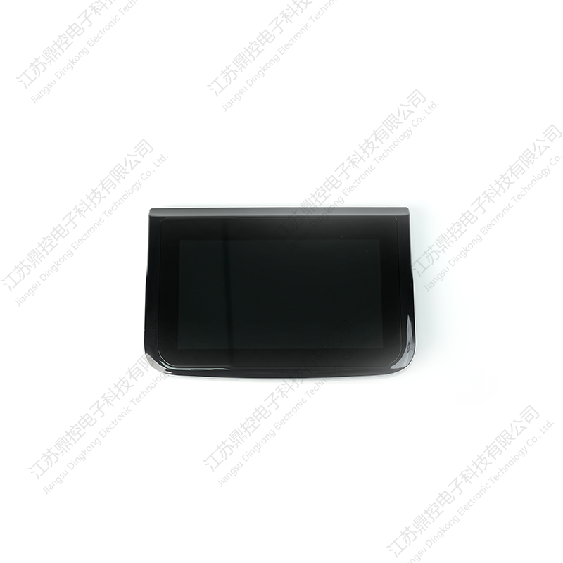 7-Inch Capacitive Touch Screen for Vehicle SystemsAutomotive 7-inch capacitive touch screen with IPS wide-view, 10-point multi-touch, and IP65 resistance, suitable for custom UI integration in vehicle systems.View Product →
A display is a useful test case. A 7-inch capacitive touch screen sits on the same low-voltage harness as the controller it talks to, so connector type, supply voltage, and mounting depth all have to be fixed on one drawing before either part is released. The same logic applies across a custom car electronics program: harness, switch gear, control module, and human-machine interface are specified together or debugged together.
Electric vehicle wiring rewards a short list of decisions made early: the correct voltage domain, an insulation class above system voltage with margin, a shield terminated at both ends, and a connector that physically proves it is seated. Everything after that is routing, documentation, and test data. Handle those four items with real numbers rather than assumptions, and a harness stops being the fragile part of the build.
1: Introduction – Enhancing Comfort and Convenience with Car Armrests The Importance of Comfort in Modern Driving In today’s automotive landscape,...
READ MOREI. IntroductionThe automotive industry is undergoing constant evolution, with a growing emphasis on vehicle maintenance and personalization. For car o...
READ MORE1. Introduction The Tesla Model 3 and Model Y have quickly become two of the most popular electric vehicles on the market. With their sleek designs, i...
READ MORE
Jiangsu Dingkong, No.1, Menlouxia, Changjing Town, Jiangyin City, Jiangsu Province, China
Copyright © 2024 Jiangsu Dingkong Electronic Technology Co., Ltd. All Rights
Reserved.
 Auto Aftermarket Accessories Manufacturers