

 English
 中文简体
中文简体1: Introduction – Enhancing Comfort and Convenience with Car Armrests The Importance of Comfort in Modern Driving In today’s automotive landscape,...
READ MOREOct 10, 2026
You have the trim panel off, the old head unit is loose in your hand, and behind it sit two black plastic blocks with eight flat contacts each. That pair is the ISO plug, and it decides whether the radio in your shopping cart is a ten-minute job or an afternoon with a multimeter on the driveway.
Here is the short version before the detail. An ISO plug is the standardised twin 8-pin connector defined by ISO 10487. One block carries permanent 12 V, ignition-switched 12 V, ground, illumination and a remote turn-on output; the other carries four speaker channels. When both the car and the new radio use it, the two halves simply click together. When they do not, you need a vehicle-specific adapter harness. And when the permanent and switched power contacts are reversed, the radio will forget its presets every time you switch off the ignition.
Content
ISO 10487 describes a pair of 8-way connectors, keyed and latched so they cannot be inserted the wrong way round. The standard dates from the late 1980s, when European head units were still wired individually and installers were tired of splicing into factory looms. Two decades of European and Asian cars adopted it, which is why a 1998 hatchback and a 2006 sedan can share the same radio plug.
It was never universal, though. From roughly 2000 onwards, Volkswagen, Audi, BMW and Mercedes-Benz moved to a 40-pin Quadlock housing that carries power, speakers, CAN data and steering-wheel signals in one shell. Many Japanese and Korean models use their own multi-pin blocks, sometimes split into a 10-pin power section and a separate speaker plug. The ISO format survives because the aftermarket still sells into older vehicles, and because adapters from Quadlock and OEM connectors down to ISO are cheap and widely stocked.
| Contact | Function | Practical notes |
|---|---|---|
| A1 | Speed pulse (GALA) | Used by some OEM radios for speed-dependent volume; often empty |
| A2 | Telephone mute input | Rarely wired in aftermarket looms |
| A3 | Reverse signal | Only relevant on navigation-equipped units |
| A4 | Permanent +12 V (terminal 30) | Must stay live with the key removed; feeds station memory |
| A5 | Antenna or amplifier remote output | Signal only, typically under 300 mA |
| A6 | Illumination or dimmer input (terminal 58) | Dims the display together with the dash lights |
| A7 | Ignition-switched +12 V (terminal 15) | Live only with the key in ACC or ON |
| A8 | Ground (terminal 31) | Should measure below 1 ohm to the chassis |
| B1 / B2 | Rear right + / − | Polarity matters more than the label on the wire |
| B3 / B4 | Front right + / − | Keep pairs twisted or bundled together |
| B5 / B6 | Front left + / − | Keep away from the power contacts in the loom |
| B7 / B8 | Rear left + / − | Check with a fader sweep after installation |
Almost every ISO-related failure traces back to three contacts: A4, A7 and A8.
With the key out of the ignition, A4 should read battery voltage, typically 12.4 to 12.6 V on a healthy lead-acid battery and around 13 V on a charged lithium pack. A7 should read zero. Turn the key to ACC and A7 should rise to the same voltage while A4 holds steady. If those two are the other way round, the symptoms are unmistakable: the clock and preset stations reset every time you park, and some units refuse to switch on until the ignition is cycled.
The fix is not to cut the factory loom. Most ISO adapter pigtails have a small release tab on each crimped terminal, so you can lift the tab, slide the A4 and A7 contacts out of the housing and swap them. That takes two minutes and keeps the car reversible.
Measure resistance from A8 to bare metal on the chassis. Under 1 ohm is good; anything higher points to a corroded stud or a ground that runs back through a shared lighting circuit. A weak ground rarely stops the radio working. It shows up as alternator whine that rises and falls with engine speed, or as a faint click through the speakers when the indicators flash.
Match the adapter to the car, not to the radio. A Quadlock-to-ISO lead solves the physical connection, but if you also want the steering-wheel buttons to keep working, you need an interface module that reads the vehicle's CAN or resistance-ladder protocol and converts it into the radio's remote input. Those are two separate purchases, and installers routinely forget the second one.
Current capacity is the other thing people underestimate. A typical single-DIN or double-DIN head unit draws roughly 5 to 10 A at high volume, and ISO power contacts are usually rated for about 15 A in a 0.75 mm² (18 AWG) harness. Speaker runs can be thinner, closer to 0.5 mm². Contact A5 is a control signal rather than a power feed, typically sourcing under 300 mA, so a 200 W amplifier needs its own relay and a fused supply taken from the battery.
Where the factory loom has already been damaged, or where the build is a custom dash rather than a straight swap, a made-to-length harness is usually cheaper than repairing spliced wiring later. Custom looms are also the normal route when a vehicle uses a connector that no off-the-shelf adapter covers.
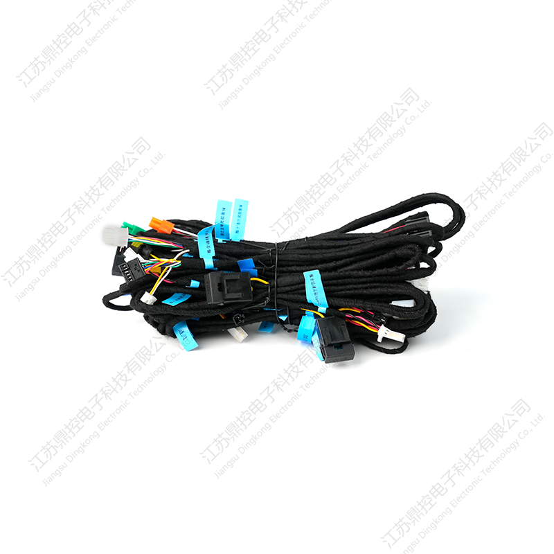 Vehicle Electronic Wiring Harness for Tesla, Mercedes-Benz, and BMWRelevant when factory wiring is damaged or a custom dash needs a tailored loom, with plug-and-play connectors for Tesla, Mercedes-Benz, and BMW.View Product →
If your vehicle uses Quadlock, a 10+6 block or a proprietary connector, and you never intended to change the head unit, the ISO plug may be irrelevant to your project. In that case the more practical goal is usually to add control and display functions without touching the radio circuit at all.
This is where a standalone capacitive touch screen earns its place. Panels from 4 inches up to 7 inches can be mounted in an armrest, a rear console or a custom dash insert and driven over CAN or RS485, leaving the factory head unit and its wiring untouched. Because such panels are not tied to the radio's power contacts, they sidestep the A4 and A7 question entirely, which is worth knowing before you commit to replacing a head unit that still works. A short primer on what a car touch screen can control is useful reading at that stage.
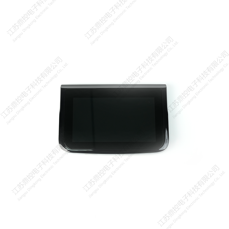 7 Inch Car Capacitive Touch Screen with IPS DisplayUseful for armrest, rear-console, or custom-dash installations where a standalone touch panel avoids disturbing a working factory head unit.View Product →
Before you order anything, write down four facts: the vehicle's year, make and model; a photograph of the existing connector with a ruler beside it; the measured voltages on A4, A7 and A8; and whether you need steering-wheel control or an amplifier feed. Those four answers decide whether the job is a plug-and-play swap or a harness build.
If the answer is a harness build, buy it from a supplier who crimps the correct terminals instead of soldering inline, and ask for the pinout in writing so the drawing can be checked against the car. Suppliers already working across custom automotive electronics, harnesses and dash hardware tend to ship a loom that matches the diagram you send, which removes the guessing that makes ISO jobs go wrong in the first place.
1: Introduction – Enhancing Comfort and Convenience with Car Armrests The Importance of Comfort in Modern Driving In today’s automotive landscape,...
READ MOREI. IntroductionThe automotive industry is undergoing constant evolution, with a growing emphasis on vehicle maintenance and personalization. For car o...
READ MORE1. Introduction The Tesla Model 3 and Model Y have quickly become two of the most popular electric vehicles on the market. With their sleek designs, i...
READ MORE
Jiangsu Dingkong, No.1, Menlouxia, Changjing Town, Jiangyin City, Jiangsu Province, China
Copyright © 2024 Jiangsu Dingkong Electronic Technology Co., Ltd. All Rights
Reserved.
 Auto Aftermarket Accessories Manufacturers