

 English
 中文简体
中文简体1: Introduction – Enhancing Comfort and Convenience with Car Armrests The Importance of Comfort in Modern Driving In today’s automotive landscape,...
READ MORESep 28, 2026
A door harness from a one-year-old fleet vehicle comes back with an intermittent power window fault. The technician opens the convoluted tubing and finds two abraded wires shorting against a sharp bracket edge. The repair takes a few dollars' worth of wire and tape, but diagnosis, downtime, and lost customer trust cost far more. The same story repeats across the automotive market every week: cable harness assembly quality is decided long before the final test. It is built into material selection, process discipline, connector choice, and design review. Buyers and engineers who understand how a harness is made make better sourcing decisions.
Content
A cable harness assembly, also called a wire harness or wiring loom, groups individual wires into one routed structure that carries electrical power and signals between components. A typical harness contains wires cut to precise lengths, terminals crimped to each end, connector housings, protective tape or sleeving, and often grommets, clips, fuse holders, or relays.
In a modern vehicle, nearly every electrical function depends on a harness: engine control, door locks, seat adjustment, infotainment, lighting, and sensors connect through bundled conductors that must fit a specific cavity and tolerate vibration and temperature swings. A single poorly crimped terminal in a seat harness can produce the same intermittent symptoms as a failed switch or motor, which is why process discipline matters as much as design.
Buyers often use the two terms interchangeably, but the physical construction differs in ways that affect cost, durability, and repair. Understanding the distinction prevents specifying the wrong product for a defined mounting space or exposure condition.
| Characteristic | Cable Harness | Cable Assembly |
|---|---|---|
| Structure | Loose wires bound with tape or sleeving | Cable with a continuous outer jacket |
| Terminations | Discrete connector housings per wire group | One molded or sealed connector at each end |
| Protection | Moderate; added sleeves or conduits | High; jacket resists abrasion and moisture |
| Service | Individual wires can be replaced | Usually replaced as a complete unit |
For automotive body and interior systems, a harness is usually the right choice because loose wires can be routed around brackets, clipped at intervals, and customized per trim level. A cable assembly suits a single protected run that must resist constant flexing. Many vehicle projects need both.
Commercial harness production follows a sequence of operations that must hit tolerances measured in millimeters or fractions of a second. Skipping a step or speeding up a stroke is how latent defects enter a product that may only fail months later.
Although automation handles wire cutting, stripping, and crimping reliably, routing and bundling still require skilled operators. A harness built by hand with care routinely outlasts an automated product that was designed without considering how it will be routed in the vehicle.
A harness that passes a final continuity test can still fail in service if the terminal crimp is weak or the wire insulation was nicked during stripping. Quality control therefore covers both direct testing and process verification. The widely referenced fabrication standard IPC/WHMA-A-620 defines acceptable levels of crimp deformation, insulation damage, and connector seating.
Automotive conditions amplify small defects. An engine bay harness sees continuous temperatures near 100°C, while a door harness flexes tens of thousands of times over a vehicle's life. The margin between reliability and a warranty problem is often a crimp height difference of 0.1 mm or a missing wrap of tape.
The design phase determines whether a cable harness assembly can be manufactured consistently and installed without problems. Several parameters should be decided before a single wire is cut.
Each circuit needs a wire gauge matched to its current, with a voltage drop within the component's tolerance over the full wire length. Shared grounds must be sized for the sum of the currents they carry, and CAN bus pairs need twisted construction so control modules receive reliable data.
The harness environment defines the protection level. Interior harnesses can use basic tape and clips; underhood and door harnesses often need convoluted tubing, abrasion-resistant braid, and sealed connectors. A well-built harness can fail in weeks if it is clipped to a hot exhaust line or pulled across a sharp edge.
Connectors must be reachable with the glove box, seat, or trim installed, and wiring should allow enough slack for removal and reinstallation. When an aftermarket team plans to replace a factory power seat system with an upgraded unit, the harness must match the original connectors and gauge selections.
Off-the-shelf harnesses rarely match a vehicle's cavity layout, connector family, or trim configuration. Custom manufacturing starts with the wiring diagram, a mechanical envelope, and the connector families of the target platform. A vehicle electronic wiring harness for Tesla, Mercedes-Benz, or BMW is a typical starting point for conversion or retrofit programs because the original connectors can be matched and the gauge layout adapted to added loads.
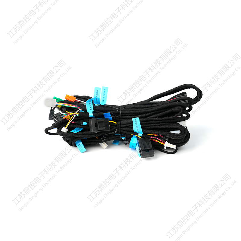 Custom Vehicle Electronic Wiring Harness for Tesla, Benz, BMWThis harness uses 99.99% oxygen-free tin-plated copper, supports 1A-150A current, 600V rating, IP67 waterproofing, and custom lengths and connectors. It is ideal for retrofit or replacement programs needing matched original connectors and adapted gauge layout.View Product →
When a program adds electric seats, voice-controlled interiors, or driver assistance devices, the power and data demands usually exceed what the stock harness was designed to carry. A custom harness built with the correct wire gauge, fusing, and shielding protects the vehicle control modules from brownouts and noise.
Suppliers that also design control electronics can validate the harness together with the receiving unit, removing a common source of integration faults. A matched control unit with its own connector layout and communication interface simplifies the system design.
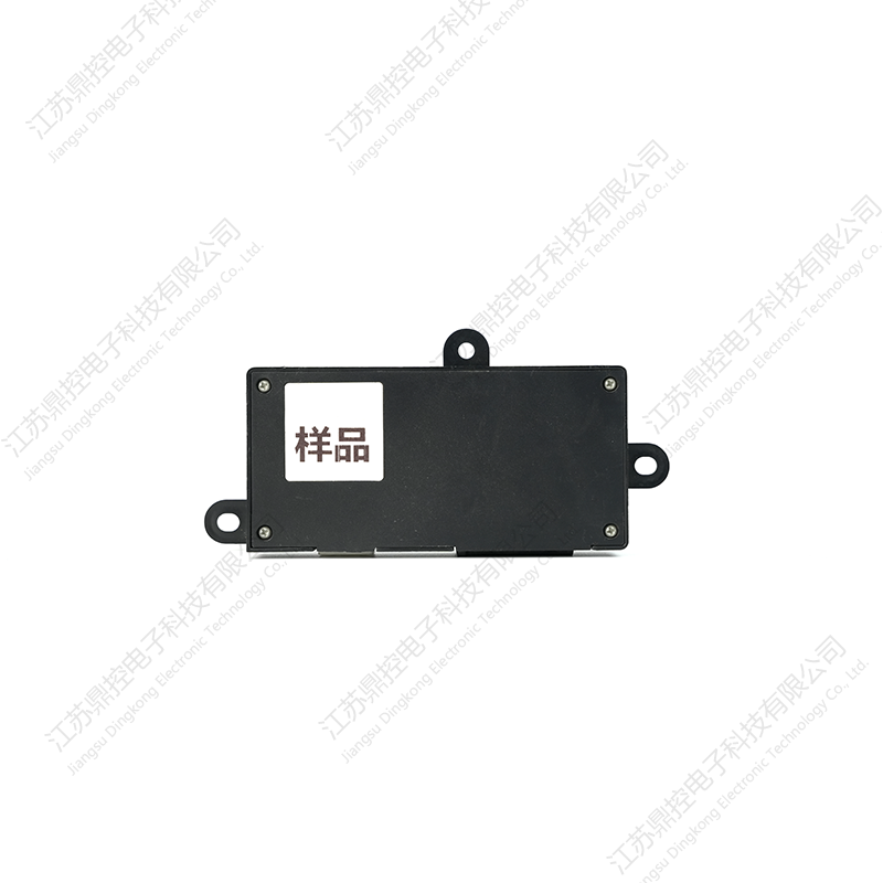 CYZ-A Vehicle Control Unit for 12V/13V SystemsThis control unit supports 12V and 13V inputs and manages premium seating, ambient lighting, and soft-close doors. It features an industrial-grade chip for accurate signal transmission, compact design, and passed multiple reliability tests, making it a dependable choice for vehicle electronics customization.View Product →
The best supplier for a cable harness assembly is not the one with the fastest quote, but the one that documents a controlled process. Confirm that the factory performs crimp pull testing, maintains die sets matched to each terminal, and follows IPC/WHMA-A-620 as a written inspection standard.
Harness failures are rarely dramatic. They appear as flickering lights, slow windows, or intermittent sensor readings that are expensive to chase. A disciplined cable harness assembly process removes that uncertainty. For vehicle programs, retrofit business, and custom electronics projects, the difference is the engineering and quality control around the wire.
1: Introduction – Enhancing Comfort and Convenience with Car Armrests The Importance of Comfort in Modern Driving In today’s automotive landscape,...
READ MOREI. IntroductionThe automotive industry is undergoing constant evolution, with a growing emphasis on vehicle maintenance and personalization. For car o...
READ MORE1. Introduction The Tesla Model 3 and Model Y have quickly become two of the most popular electric vehicles on the market. With their sleek designs, i...
READ MORE
Jiangsu Dingkong, No.1, Menlouxia, Changjing Town, Jiangyin City, Jiangsu Province, China
Copyright © 2024 Jiangsu Dingkong Electronic Technology Co., Ltd. All Rights
Reserved.
 Auto Aftermarket Accessories Manufacturers